ISO 834 BS 476 قسمت 20&22 مواد و سازه های ساختمانی کوره آزمایش مقاومت آتش عمودی
ASTM E119 ISO 834 تجهیزات آزمایش قابل احتراق مقاومت عمودی آتش در مقیاس بزرگ
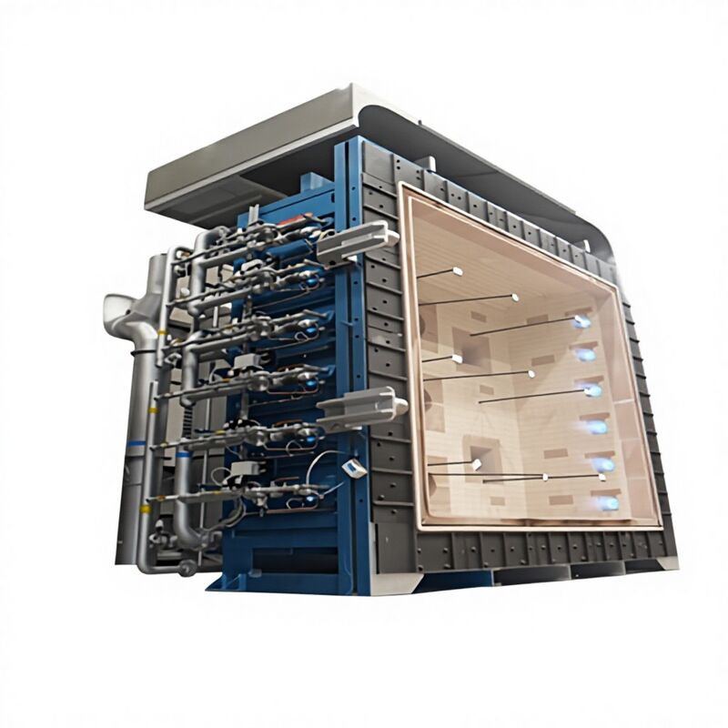
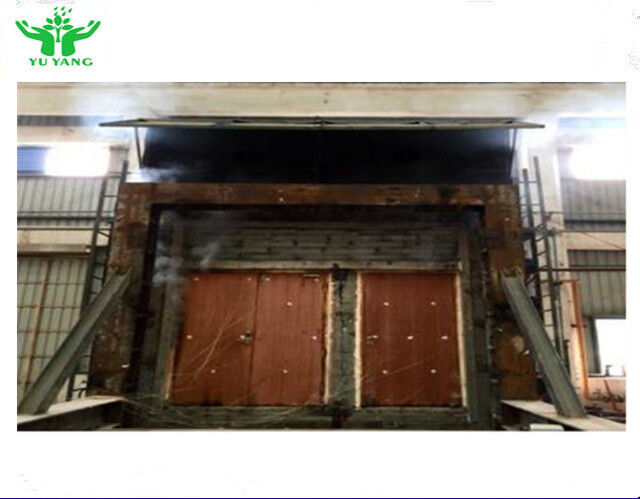
کوره آزمایش مقاومت آتش عمودی کامل که برای استفاده از سوخت های مایع یا گازی طراحی شده و قادر به گرم کردن عناصر جدا کننده عمودی در یک طرف است.پوشش کوره از مواد آتش شکن با تراکم کمتر از 1000 kg/m3 تشکیل شده است، که بیش از 70 درصد از سطح درونی را تشکیل می دهد.
برای ایجاد شرایط قرار گرفتن در معرض آتش با توجه به قرار گرفتن در معرض گرما و فشار، مطابق با استانداردهای CEN، ISO و IMO ساخته شده است. حداقل ابعاد داخلی اتاق:عرض 4000 میلی متر × ارتفاع 3000 میلی متر × عمق 1000 میلی متر.
در واحد های ماژولار در کارخانه ساخته شده و در کانتینرهای 40 فوت HC ارسال می شود. واحد های ماژولار بر روی یک پایه قوی که توسط مشتری در هنگام ورود آماده می شود، جمع آوری می شوند.
پوشش فولادی کوره
ساخته شده از بخش های فولادی ساختاری و صفحات طراحی شده برای استفاده قوی. صفحات فولادی با کانال های C، I-beam و بخش های فولادی تقویت شده اند تا از تحریفات ساختاری ناشی از گرما جلوگیری کنند،مخصوصاً در اطراف سوراخ های سوختن، ترموپول ها، سنجه های فشار، و پورت های مشاهده.
صفحه های آهن ریخته به صورت بیرونی جلو برای فراهم کردن یک سطح قوی برای نصب قاب بازدارنده نمونه آزمایش می شود.چهار مجموعه از کلیمپ های رول خود قفل کننده به طور ایمن قاب بازدارنده نمونه آزمایش را بر روی جلوی کوره نگه می دارند.
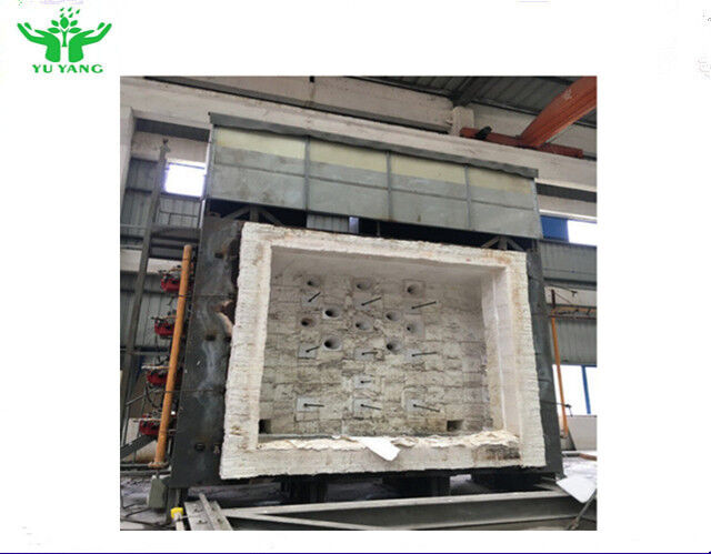
عایق کوره
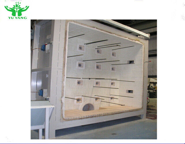
پوشش آتش گیر شامل سنگ های عایق با درجه حرارت 1430 درجه سانتیگراد با تراکم 900 کیلوگرم / متر مکعب در سطح داغ است که توسط عایق پارچه فیبر بر روی سطح سرد پشتیبانی می شود.دمای پوشش بیرونی کمتر از 75°C در دو ساعت پس از آزمایش آتش در 1200°C باقی می ماند.
بلوک های پیش ساخته شده با دمای بالا ساخته شده از فلز تقویت شده از فیبر های آتش گیر که در درجه 1600 درجه سانتیگراد درجه بندی شده اند، محیط باز شدن کوره را از سایش مداوم توسط قاب نمونه آزمایش محافظت می کنند.
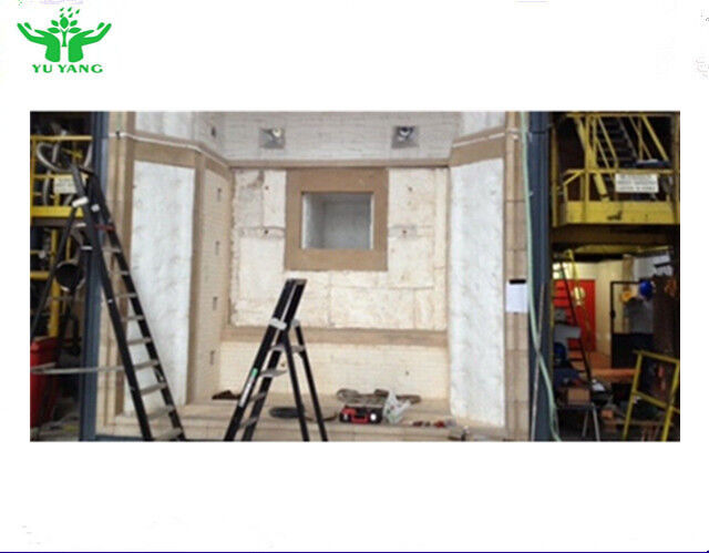
چهار پورت مشاهده در دیوار پشت کوره، بینایی کامل نمونه آزمایش را در طول آزمایش های آتش فراهم می کند. هر یک از آنها دارای صفحه شیشه ای کوارتز شفاف است که در یک محفظه خنک شده و عایق بندی شده قرار دارد.
دریچه گازهای خروجی کوره و خروجی گاز دود با عایق فیبر سرامیکی با جرم حرارتی پایین ( چگالی: 128 کیلوگرم / متر) پوشش داده شده است.
نقاشی
محفظه بیرونی کوره با رنگ رنگ نقره ای رنگ درجه حرارت بالا رنگ شده است.
سیستم کنترل فشار
سه دمپر فولادی مقاوم به گرما که در دود استخراج ساخته شده اند کنترل دقیق فشار اتاق کوره را امکان پذیر می کنند.پورت های استخراج تنظیم پذیر اجازه می دهد تا تغییرات نرخ استخراج در موقعیت های مختلف در اتاق. دامپرهای موتور شده از اتاق کنترل از طریق سیستم مدیریت داده های آزمایش آتش تنظیم می شوند.
سیستم احتراق
دوازده سوزنده پیش مخلوط LPG / گاز طبیعی ارائه شده است: 6 واحد در دیوار سمت چپ کوره (3m × 1.3m) و 6 واحد در سمت راست نصب شده است.
تجهیزات احتراق شامل:
- 12 سوزنده مخلوط کننده گاز
- 12 دریچه های کنترل تعادل هوا
- 12 دریچه های کنترل تعادل گاز
- 12 تنظیم کننده گاز خلبان
- 12 دریچه های خاموش کردن گاز برای سوزنده ها
- 12 کنترل ایمنی سوختن گاز کاملا اتوماتیک
- 12 روشن کردن جرقه، ترانسفورماتور و کابل
- 12 اسکنر ماوراء بنفش
- 12 لوله هوا انعطاف پذیر
- 12 لوله گاز انعطاف پذیر
- 12 دریچه های پروانه هوایی دستی
- 3 دریچه های خاموش گاز اصلی
- 6 سوئیچ های فشار گاز با کانکتور
- 30 مانومتر گاز
- 3 آب و هوا گاز دریچه های نسبت میکرو
- 3 هوافشان احتراق
- 3 فیلتر گاز اصلی
- 3 تنظیم کننده گاز اصلی
سوزنده ها برای گاز طبیعی یا مایع نفتی مناسب هستند (به صورت سفارش توسط مشتری تایید می شود).بلوک های سوزنده از مواد قابل ریخته سازی که حاوی 80٪ آلومینیوم هستند ساخته می شوند، طراحی شده برای مقاومت در برابر شوک حرارتی منظم.
سیستم توزیع گاز و هوا
سه فن هوا به سیستم احتراق هوا می دهد و اتمسفر کوره را اکسیژن می دهد تا الزامات استاندارد آزمایش آتش برای حداقل سطوح اکسیژن را برآورده کند.فن ها از پنل کنترل احتراق در اتاق کنترل کوره کار می کنند.
تمام لوله های هوایی متصل به یکدیگر برای آسان بودن دستکاری از پیش ساخته شده اند و در محل متصل می شوند.
مسیر لوله گاز داخلی قبل از ساخت با مشتری مورد بحث قرار می گیرد تا با طرح ساختمان آزمایشگاه مطابقت داشته باشد.با لوله های گاز و هوا که به رنگ های شناسایی بین المللی رنگ شده اند.
سیستم استخراج و شومینه
سیستم استخراج شامل یک فن استخراج و لوله دود برای کنترل تخلیه گاز های احتراق داغ از کوره به دودخانه در طول آزمایش است.فن استخراج از اتاق کنترل از طریق حالت کار خودکار یا دستی فعال می شود.
لوله گاز خروجی بین فن اکستراژ و کوره از بخش های فولادی از پیش ساخته شده ساخته شده است که در محل جمع آوری شده اند و برای مقاومت در برابر چرخه های منظم گرم کردن و خنک کردن عایق بندی شده اند.و با رنگ درجه حرارت بالا برای حفاظت از خوردگی رنگ شده است.
یک محرک کششی گاز های خروجی را برای کاهش دمای قبل از عبور به فن استخراج رقیق می کند.دودکش با قطر داخلی 950mm و حداقل ارتفاع 3 متر بالای سقف می تواند بر اساس درخواست ارائه شود، یا نقشه های ارائه شده برای ساخت مشتری. شومینه از فولاد خفیف ساخته شده است، آزاد ایستاده است و نیاز به آماده سازی پایه برای بار باد و خاک استقرار دارد.از نظر ایمنی تا ارتفاع 3 متر جدا شده است.
پلتفرم / راهرو
پلتفرم / پیاده رو کامل دسترسی ایمن به پورت های مشاهده و ابزار در دو طرف و پشت کوره را فراهم می کند. شامل دستبندها، کفپوش ها و سطح مقاوم به لغزش برای ایمنی اپراتور است.
ترمومترهای صفحه ای
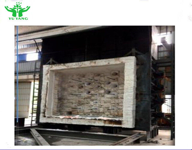
نه ترمومتر صفحه ای که در استانداردهای CEN مشخص شده اند، به طور مساوی بر روی ناحیه در معرض نمونه قرار دارند.متصل به سیستم جمع آوری داده های کامپیوتری برای نظارت و ثبت دمای کوره قبل و در طول آزمایش.
ترموپول های کوره
۹ ترموپول کوره ای که با مشخصات سازمان بین المللی دریایی (IMO) مطابقت دارند، در دیوار عقب در موقعیت های مورد نیاز قرار دارند و با لوله های مقاوم به گرما برای به حداقل رساندن تحریف محافظت می شوند.متصل به سیستم جمع آوری داده های کامپیوتری برای نظارت و ثبت دمای.
جعبه های اتصال ابزار
جعبه اتصال ابزار واقع در نزدیکی کوره (از گرما محافظت شده) امکان اتصال آسان تمام ابزار را فراهم می کند.شامل اتصالات شماره گذاری شده فردی است که به اتصالات مربوطه در اتاق کنترل مرتبط است.، متصل به سیستم جمع آوری داده های کامپیوتری است.
ترمومتر دمای محیط
دمای محیط، دمای آزمایشگاه را قبل و در طول آزمایش ها کنترل و ثبت می کند.
دنده های فشار
دو تغییر دهنده فشار که در موقعیت هایی قرار دارند که الزامات استاندارد مربوطه را برآورده می کنند. در صورت لزوم می توانند بین موقعیت ها حرکت کنند.متصل به سیستم جمع آوری داده های کامپیوتری برای نظارت و ثبت در فواصل از پیش تعیین شده.
نقاط استفاده از تحلیلگر اکسیژن
خط نمونه گیری دائمی با اتصال امکان اتصال تحلیلگر اکسیژن به گاز های نمونه گیری را فراهم می کند.سیگنال تولید شده در سیستم مدیریت داده های آزمایش آتش ثبت می شود و بر روی صفحه نمایش نمایش داده می شود..
دستگاه اندازه گیری انحراف
دستگاه لیزر قابل حمل انحراف نمونه را از موقعیت اصلی در مرکز اندازه گیری می کند.
دستگاه زمانبندی
دستگاه زمانبندی نمایشگر بزرگ قابل مشاهده برای کارکنان آزمایش و در عکس های آزمایش. به سیستم مدیریت داده های آزمایش مقاومت به آتش متصل برای اطمینان از شروع همزمان.زمان گذشت را به نزدیکترین ثانیه نشان می دهددر عرض 1 ثانیه در ساعت.

 پیام شما باید بین 20 تا 3000 کاراکتر باشد!